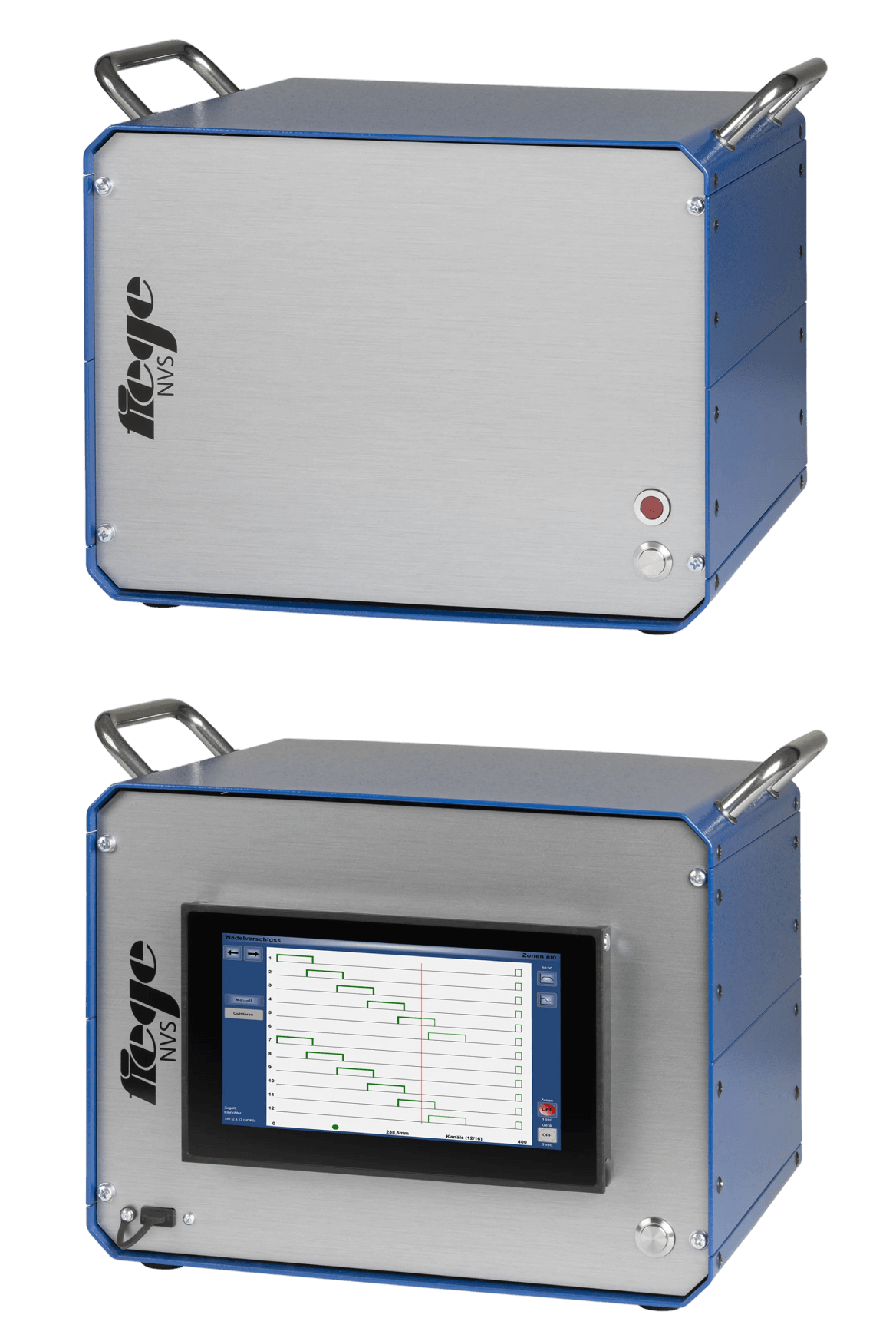
Needle valve-control – all in one mould data record

Let’s start with the main features:

  • compact add-on device as “NVS” or as stand-alone version “NVS-TP”
  • for 4 to 32 zones in steps of 4
  • 24V DC control mechanism
  • Operation via hot runner controllers or via the touch display on the front (NVS-TP)
  • Flexible visualisation

Ahead of the competition - It’s your choice:

One of the most recent Fiege electronic top performers is the stand-alone version of the proven needle shut off control of the NVS series. The NVS-TP version has its own touch display and can therefore be used completely independently of the hot runner controller. The proven NVS version extends any existing temperature controller (software version 3.0 and above) by the functionality of a needle shut off control. With this development, Fiege yet again sets the standard in terms of flexibility and ease of operation. The devices of the NVS series can be used irrespective of the hot runner manufacturer.

Needle valve-control

Technical data

Housing:
Aluminum, colour RAL 5010 gentian blue,
special colours available upon request

Dimension/weight:
Acc. “Device model”, table (see below)

Channels:
4 to 32 in 4 steps

Operation / Visualisation:
NVS: Via any hot runner controllers of the “TP” or “VARIO” series (program version 3.0 and later)
NVS-TP: Via the touch display on the front

Power outputs:
24VDC/1.25A = 30W per channel

Stroke control::
Up to 1000 mm, accuracy 0.1mm

Time control:
Up to 600 secs, accuracy 0.1 sec

Control inputs:
Contact inputs for: Machine release,
injection start and start holding pressure

Alarm notification:
NVS: Alarm contact and message on the connected hot runner controller
NVS-TP: Shows on display as well as dry alarm contact

Interfaces:
NVS:
1x Ethernet for future extensions (1x Ethernet for connection of the hot runner controller)

Mould connection:
See diagram of the equipment or customised depiction upon request

Power supply:
230 VAC +10…-10%, 50…60 Hz, 1P / N / PE,
other voltages upon request

Control fuse:
Safety fuse MT 6.3 A, 5 x 20mm

Power supply:
Mains cable with schuko plug length 4m

Ambient temperature:
Operation 0..+50°C, , storage -30.. +70°C

Air conditioning Application class:
According to DIN 40 040, relative humidity, ≤ 75% in the annual average, no condensation

Protective system:
IP20

Protection class:
I

The structure

NVS User interface:

Thanks to its practical carry handles, this compact add-on device in a handy stack format can be easily transported.

  1. Hot runner controller
  2. Visualitation
  3. Needle Valve Control System

NVS Device rear view:

Two standard Ethernet connections secure the connection to the hot runner controller as well as to the external application.

  1. Solenoid valve connection
  2. Power supply
  3. Way sensor connection
  4. Controlling signals of the machine
  5. 2 x Ethernet connection

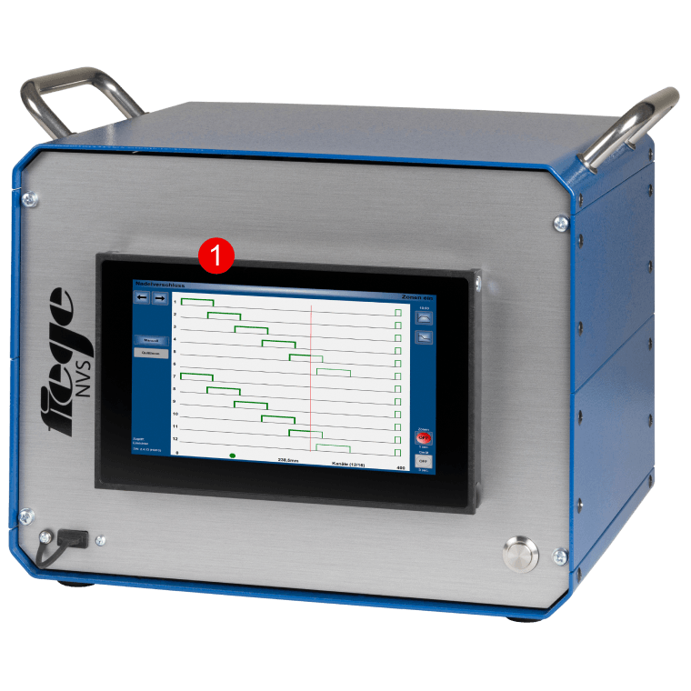
NVS-TP User interface:

  1. Visualisation and needle shut-off- control system in one housing

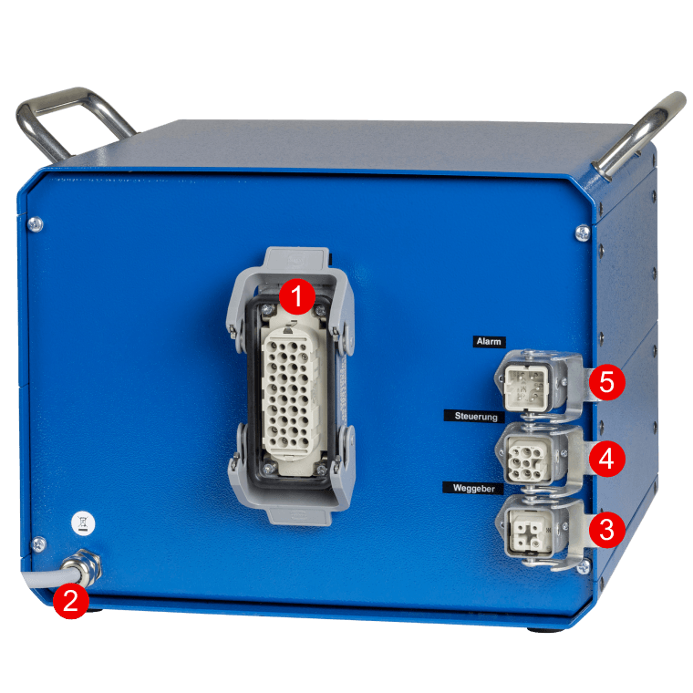
NVS-TP Device rear view:

  1. Solenoid valve connection
  2. Mains connection
  3. Way sensor connection
  4. Controlling signals of the machine
  5. Alarm output

The rear side may differ from this representation depending on the customer specification.

Needle valve-control

Device models:

ChannelsNVSItem no.NVS-TPItem no.Size(mm) W x H X d
Weight ca..(kg)
4NVS 41500-0000-04NVS 4 TP1520-0000-04341 x 260 x 2508
8NVS 81500-0000-08NVS 8 TP1520-0000-08341 x 260 x 2508
12NVS 121500-0000-12NVS 12 TP1520-0000-12341 x 260 x 2508
16NVS 161500-0000-16NVS 16 TP1520-0000-16341 x 260 x 2508
20NVS 201500-0000-20NVS 20 TP1520-0000-20341 x 345 x 25012
24NVS 241500-0000-24NVS 24 TP1520-0000-24341 x 345 x 25012
28NVS 281500-0000-28NVS 28 TP1520-0000-28341 x 345 x 25012
32NVS 321500-0000-32NVS 32 TP1520-0000-32341 x 345 x 25012

Features

  • 24V DC control mechanism for pneumatic and hydraulic solenoid valves
  • NVS: Control, operation and mould administration takes place via the hot runner controllers of the “TP” or “VARIO” series (program version 3.0 and later)
  • NVS TP: Operation and mould administration via the touch display on the front
  • The injection process can be controlled by means of screw strokes or injection time
  • There are 5 switching operations available per channel and cycle
  • Manual control is an element for starting the system and during maintenance work

Accessories

Product
Way sensorup to 1000 mm upon request
Connection cable for way sensorupon request
Connection cable for machine signalsupon request
Connection cable for valve actuationupon request

0000: will be replaced by a custom version number when the order is placed.

Subject to modifications.

Downloads

Find comprehensive product information here:

Contact

Do you have any questions about our products? Our service advisors will be happy to help.

+49 6201 259 58-19 To the form